Radio
Frequency Theory
For Surveillance Systems
Introduction:
Radio
systems exist in form of transmitters and receivers or combined transmitters
and receivers also called transceivers. The radio frequency (RF) receiver must
have the ability to receive the intended signals only. Intended signals include
data and audio and other forms of meaningful signals as well. The Transmitter
and receiver must both be able to tune to one another and secure the signal
being communicated. There are various ways of accomplishing this ultimate goal
of radio communication. In the old days radio communication security was not
evolved and security was not as urgently needed as it is today. There are
probably tens and hundreds of radio signals around you now - not utilizing
security measures and radio tuning electronic circuits will make radio
communication very inconvenient if not impossible. The radio history started
with very simple forms of communication circuitries such as manually driven
continuous wave (CW) data transmitters, tuned radio frequency circuits, and the
similar. Among the latest advents and greatest accomplishments of wireless data
communications is the spread spectrum technology.
Fact: Data or audio
signals can’t travel long distance over air or cables at their own; they need
the help of higher energy and higher frequency signal that can travel
un-exhausted long distance at its own. The higher energy higher frequency
signal will give data or audio signals a safe ride to its destination. The data
or audio signals may vanish prior to reaching their destination if they travel
at their own. This is the reason the higher energy higher frequency signal is
called the carrier – it carries the audio or data un-exhausted to their
destination. The act of riding the data or audio signal on the
carrier signal is called modulation. The data or Audio is called the
modulating, and the carrier is called the modulated.
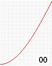
Continuous
Wave CW transmitters and receivers usually use the sinusoidal waves to transmit
and receive signal. The following wave resembles the cosine wave which is the
sine wave shifted by 90 degrees:
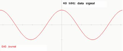
This
wave has a frequency of 868 MHz. The above CW signal can be modulated with data
or voice. The CW wave is called in this case the carrier wave. The signal to be
transmitted or communicated is not the carrier but is the data or voice signal
and usually has a much lower frequency than the CW carrier signal. For example
a 40 MHz data signal is to be communicated between the main office and the
security system inside the merchandise store:
The
radio transmitter will combine the data and carrier signals together and send
the resulted combined signal as following:
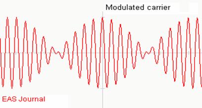
Notice
that the above modulated carrier has two frequencies, unlike the original carrier
signal and the data signal. An ON-OFF Keying (OOK) modulation is another method
used to send data over the air or cables. This is also called Amplitude
Modulation (AM). The same 868 MHz carrier above could be used for example to
send the letter A from the transmitter to the receiver. The letter A data is represented by the ASCII value of 41 hex of binary
digital code 01000001:
The binary 41 data above could be used to modulate the following carrier wave signal of 915 MHz:
The RF transmitter will send to the air the following modulated signal via the antenna:
The
above method is not pretty secured against hackers and thieves so data
scrambling, encoding and decoding schemes along with random number generators
could be used to establish secured communication. For example the word “HELP”
could be wirelessly sent as “z4&0d$” instead. One issue with that is the
speed may then be reduced. To overcome this issue a modulation scheme called IQ
could be used to speed up the communication and processing capabilities for a
dramatically reduced latency time. The IQ stands for In Phase / Quad Phase,
where Quad Phase refers to the 90 degrees of phase shift in the carrier
signal.
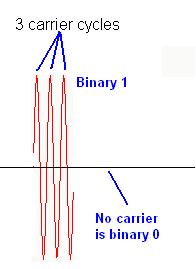
The
above example transmitted the zeros and ones bits of the letter “A”. The presence
of the carrier represented the bit 1 and the absence of the carrier represented
bit 0.
Fact:
Communication devices are required to perform
fast and secure transactions.
Depending
on the system used the rules may vary; for example the presence of the carrier
could alternately represent bit 0 and absence of carrier represent bit 1.
Whenever the presence of carrier is used to present bit one or zero the number
of the carrier cycles per bit may also vary depending on the system rules. The
larger the number of carrier cycles per bit used for this presentation the
longer the processing time is required and therefore the system latency may be
affected. Also more power will be required to transmit data for larger number
of cycles. There are many advantages and disadvantages to using larger number
of cycles per bit transmitted. Wireless features that differentiate systems
from one another include power consumption, modulation scheme, baud rate or
communication speed, communication errors and error correction, and
communication immunity against adverse environment.
Radio Frequency
Heterodyning – Mixing:
Radio
and wireless systems are used to send data and audio signal to remote places.
Different methods are used to enable this transaction. These methods have
advantages and disadvantages. The application usually dictates the type of
system to use. Applications range from opening your car by the key fob,
operating the mobile phone, listening to the music, watching the highway
traffic remotely, withdrawing money from your account, reading the temperature
of the backyard, and so on. The application carries with it requirements that
demand certain wireless system characteristics. These characteristics include
cost and affordability, safety and security, immunity against electrical noise
such as high power machines, operating in hostile environment or congested
radio traffic, sending guidance data command to a guided weapon, and so on. It
is thus obvious that not all wireless systems use same electronics and
technology.
Tip: We will assign to the data and audio signals the term
“signal” only. This signal could also resembles any other source of meaningful
signal including but not limited to video signal, temperature signal, pressure
signal, light signal, and so on. All of these signals are to be communicated
and transmitted between two points at a time.
The
most commonly used modulation methods for radio and wireless communications are
the Amplitude Modulation (AM) and Frequency Modulation (FM). Both of these modulation methods share the
same modulation block diagram:
The
above diagram is an overview of how the antenna signal (also called RF signal)
is mixed (Heterodyned) with an internally generated signal by an RF circuit
called the Local Oscillator. When both of the local oscillator signal (LO) and
the Radio signal (RF) are mixed by the RF Mixer circuit the result is called
Intermediate Frequency (IF) signal:
RF
(MIXED with) LO > IF
The
IF signal has new frequency equals to the Local
Oscillator frequency less than the Radio RF frequency.
IF
frequency = LO frequency – RF frequency
The
LO signal frequency is generated by a special LO electronic circuit that allows
the LO frequency to be varied either electronically or manually. This is
similar to the tuning circuit in your radio which is connected to the knob you select
the radio station from. By rotating the knob
or pressing on the channel buttons you are actually changing the LO local
oscillator frequency. The LO frequency is usually higher than the incoming RF frequency
so the IF frequency is positive in value. The radio circuit deals with one
single IF frequency only. This unique IF frequency (signal) is used to extract
the information needed such as security data or voice. In order to provide the fixed
IF signal the LO frequency is brought up to a frequency higher than the desired
channel frequency by a fixed value. For example assume that the system’s IF of
2 MHz have channels with assigned frequencies as follow:

Channel 1 Channel 2 Channel 3 Channel 4 Channel 5
To
select channel 1 you will need to bring the LO frequency to 12 MH since LO (12)
– RF (10) = (IF) 2, and in order to tune to (select) channel 3 you will need to
bring the LO frequency to 32 MHz.
Fact: The data or audio signal is usually of much lower
frequency than the carrier frequency.
Human can only deal and interact with the common audio and data low
frequency signals, and other signals such as visual, LCD, and similar. Radio
science deals with the process of frequency conversion between the low to high
and back to low frequency as the final beneficiary of this process is human.
Basic Modulation
Techniques:
The
origin of all radio modulation techniques stem back to the AM and FM basic
modulation. AM modulation changes the carrier frequency according to the data
signal while the FM changes the carrier frequency according to the data signal.
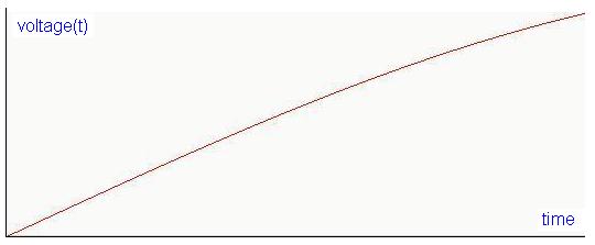
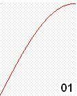
The information signal varies with time such as it could increase, decrease, or
vanish to zero. The following signal represents a temperature increase as
function of time. The temperature starts from zero at the bottom left and increases
as time goes by. This analog temperature signal is converted to a voltage
signal voltage(t) where the voltage tracks temperature
as function of time:
The
above temperature analog signal can modulate a fixed carrier signal below:
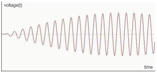
In
AM modulation the carrier frequency is kept the same but the amplitude of the
carrier is changed according to the temperature signal as follow:
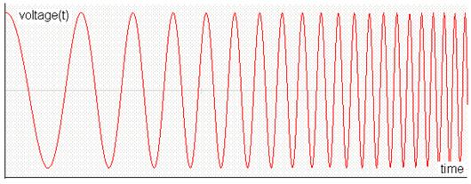
In
FM modulation the amplitude of the carrier is kept the same but the carrier
frequency is changed according to the temperature signal as follow:
The
temperature reading is then transmitted in form of radio signal and picked by
the radio receiver. The receiver then extracts the information from the radio
signal (AM or FM) by analyzing the variation in amplitude or frequency. The
same rules of amplitude and frequency variations are followed when transmitting
or receiving the data signal.
From
the above methods of AM and FM modulations different forms of radio modulations
are derived. The ON-OFF Keying (OOK) technique described above is a derived
form of AM modulation. Frequency Hopping Spread Spectrum (FHSS) is an advanced
form of FM modulation. Other modulation
techniques such as Frequency Shift Keying (FSK), Phase Shift Keying (PSK), and In phase – Out of phase (IQ) modulation, Quadrate Phase
Shift Keying (QPSK) modulation are also derived forms of FM modulation. The key
is that the sine wave is divided into equal number of sections (4, 8, 16, 32) and the correct section is used to associate the data
symbol to. Phase modulation and frequency modulation are related to one another
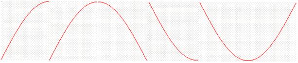
and many rules equally apply to both of them. The sine wave can be divided into
4 quarters (Quad Modulation) each of the quad having 90 degrees. Here is how
the sine wave is divided into 4 equal sections
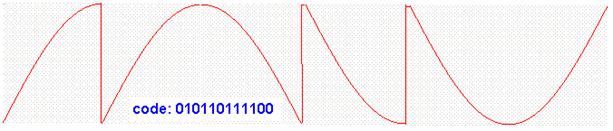
Details of the sine wave quads are used to carry useful information in the radio waves. These quads are transmitted wirelessly in series from the transmitter to the receiver. The IQ modulation could be use for very high speed communication. Each quad is assigned for example two digital bits as follow:
The
digital 010110111100 code is radio transmitted by the following radio signal:
By
doing so the power consumptions is minimized, communication speed is
multiplied, but the possibility of transmit error is increased. Here is how the
above radio signal may look like using the oscilloscope:
Different systems may have different rules and assign different bits for quad symbols.
End of Radio Frequency Theory for Surveillance Systems
Please
go to previous page and send us your comments about this presentation. Any
recommendation is appreciated.